Screen Door Closure
|
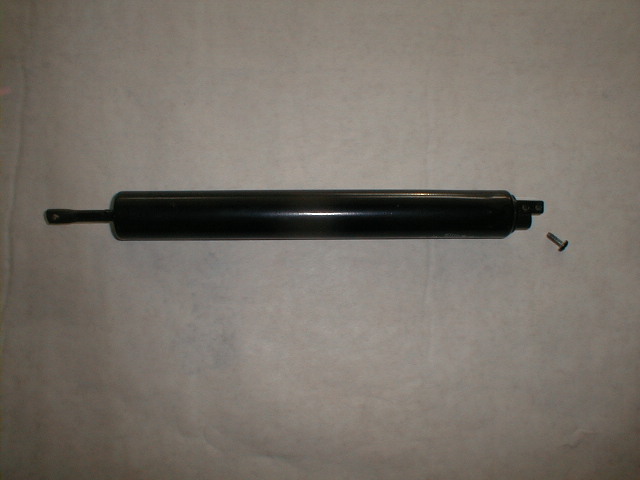
Here is an ordinary screen door closure showing the screw removed. Hacksaw the attaching point (there are 2) that extends past the screw hole so that a fitting can be put in the hole. Test the fittings fit into the hole, if it is a snug fit, just thread it forcibly in the hole. The hole is not very deep, so you may have to drill it deeper. Be sure to extend the ram so you don't put a hole in it. |
|
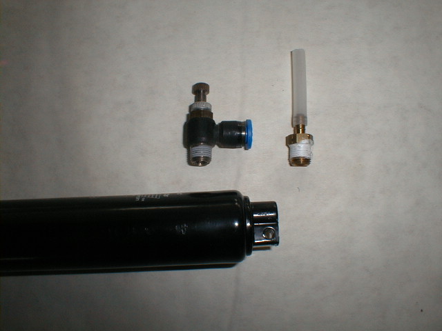
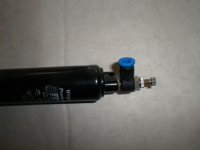
Shown here are 2 types of fittings. The black one has a speed control fitting built in. Both of these fittings accept 1/4" polyethylene tubing. The blue ring on the right angle fitting is called a "one touch" fitting. All you have to do is push the 1/4" tubing in and the blue sleeve grabs the tubing with teeth to hold it in place. The tubing is easily removed by pressing the blue sleeve outward to release the tubing and pulling the tubing out. |
|
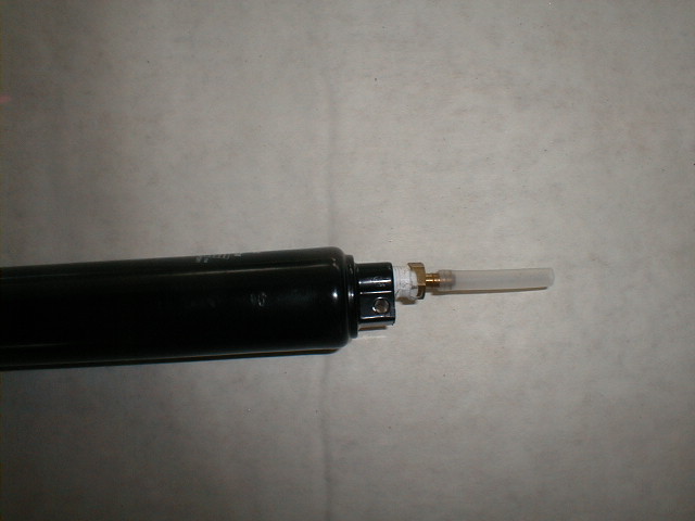
Since the fittings are brass and the screen door closure is soft aluminum you can thread the fitting in just by forcing it to make its own threads. |
|
There are many types of fittings available. I use 3/8" because they fit nicely into the screen door closure. Sometimes the hole in the closure is slightly large so when I drill out the hole to a proper depth, I keep the drill bit slightly smaller than the threads on the fitting. This allows it to make its own threads very nicely. |
|
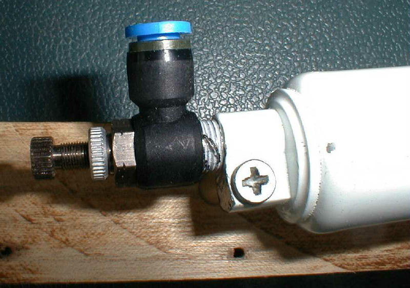
Here is another view using a white screen door closure. |
|
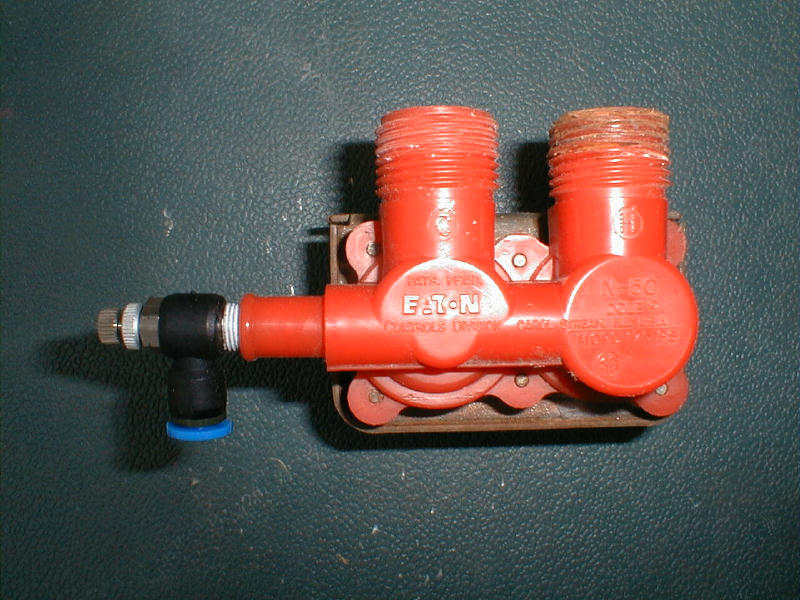
This is a picture of a washing machine water valve. This particular model accepts the threaded fitting nicely, but I can't seem to find the red ones to easily. By using the same drill bit used before you can make the hole to accept the fitting. |
|
|
This is a wooden mock up I made for demonstration purposes. This photo shows it at rest. I like making my prototypes out of wood until I get it right. It can then be transferred to metal although wood would work just fine too. |

|
This is the prop extended. |
|
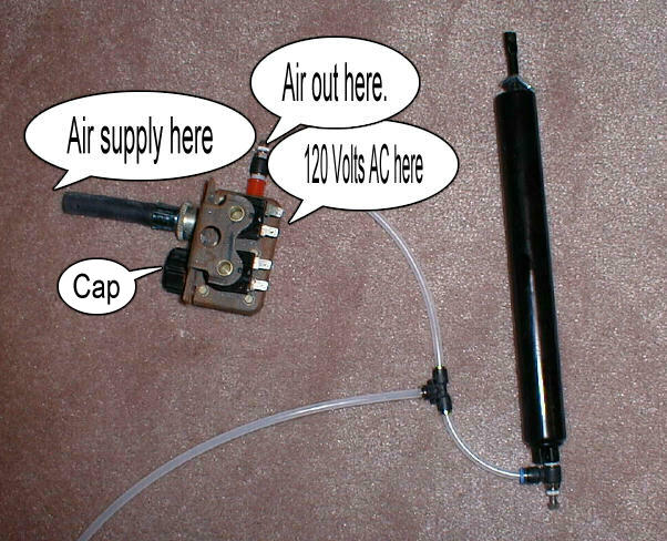
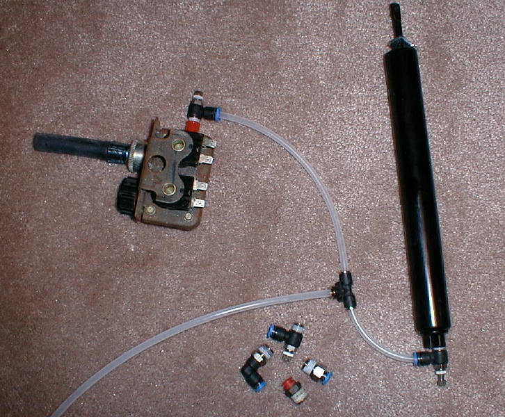
This shows a pretty much completed system. On the left side is the washing machine valve with a piece of hose attached. This is where you would attach your air supply. Just opposite you will see 2 electric connectors to attach your house power to. You only need to attach the side that is directly opposite the hose. The other hose connector has a cap you can pick up at any garden center. Remove the rubber washer and don't tighten all the way. This will allow air to escape when the power is off. And you can adjust this as desired. |
|
This is the same picture but showing a few other fittings. |
|
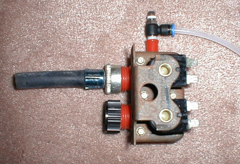
This is a close up of the washing machine valve. On the left side is the washing machine valve with a piece of hose attached. This is where you would attach your air supply. Just opposite you will see 2 electric connectors to attach your house power to. You only need to attach the side that is directly opposite the hose. The other hose connector has a cap you can pick up at any garden center. Remove the rubber washer and don't tighten all the way. This will allow air to escape when the power is off. And you can adjust this as desired. |
You can obtain these air fittings from any supply house that sells compressors, air cylinders and fittings. Check your yellow pages.
See here for a view of the fittings. Or do a search for "One touch fittings" and you should be able to find them.